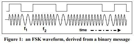
1. What's 2FSK (two frequency represent 0 and 1)

2. Connect CC1101 with Arduino
See 2ASK over the air.
3. Find frequency shift of CC1101
See 2ASK over the air.
4. Find sync word
See 2ASK over the air. The following signals all have a
1010101010101010sync word.
5. Send 2FSK bytes
Construct a FSK receiver in GNU radio:

Using the following code to send
0x01,0x02,0x04,0x08,0x10,0x20,0x40,0x80every 2 seconds. And check FSK signals over the air, the results are saved as Video. The last one pulse left shift bit by bit. The red signal was demodulated by the Quadrature Demod which can map frequency deviation to amplitude. The blue signal (binary signal) is transferred from the red signal.
#include <ELECHOUSE_CC1101_SRC_DRV.h>

byte one_byte[8][1]={{0x01},{0x02},{0x04},{0x08},{0x10},{0x20},{0x40},{0x80}};
int i=0;

void setup() {
    Serial.begin(9600);
    if (ELECHOUSE_cc1101.getCC1101()){        // Check the CC1101 Spi connection.
    Serial.println("Connection OK");
    }else{
    Serial.println("Connection Error");
    }
    ELECHOUSE_cc1101.Init();              // must be set to initialize the cc1101!
    ELECHOUSE_cc1101.setCCMode(1);       // set config for internal transmission mode.
    ELECHOUSE_cc1101.setModulation(0);  // 0 = 2-FSK, 1 = GFSK, 2 = ASK/OOK, 3 = 4-FSK, 4 = MSK.
    //Frequency error: +0.04MHz
    ELECHOUSE_cc1101.setMHZ(433.92);   // The cc1101 can: 300-348 MHZ, 387-464MHZ and 779-928MHZ.
    ELECHOUSE_cc1101.setSyncMode(2);  // 0 = No preamble/sync. 1 = 16 sync word bits detected. 2 = 16/16 sync word bits detected. 3 = 30/32 sync word bits detected. 4 = No preamble/sync, carrier-sense above threshold. 5 = 15/16 + carrier-sense above threshold. 6 = 16/16 + carrier-sense above threshold. 7 = 30/32 + carrier-sense above threshold.
    ELECHOUSE_cc1101.setCrc(0);     // 1 = CRC calculation in TX and CRC check in RX enabled. 0 = CRC disabled for TX and RX.
    ELECHOUSE_cc1101.setDRate(9.6); //9.6kbps
    ELECHOUSE_cc1101.setDeviation(5);  //5k
    Serial.println("Tx Mode");
}

void loop() {

ELECHOUSE_cc1101.SendData(one_byte[i], 1, 100);
delay(2000);
i=(i+1)%8;

}

Comment Section