I was inspired by a YouTube video, which made optical tweezers seem much easier than I'd ever thought. It indeed looks simple, but it has reasons. The ink particle is able to be tapped in the laser in part because it is initially encapsulated by water; meanwhile, it is dark, which means it could absorb more energy to vaporize the water. When the water is all gone, then the particle is trapped.
In order to capture a 5um particle, it's easier to use the geometric optics theory to get started with. So I chose the particles of a normal size (5um), which is similar to the size of an animal cell.
1. Theory
And here, what is to be analyzed is the z-axis force because the more difficult part is this. Usually, the gradient force is far more intense than the scattering force, it will push the particles forward along the direction of the beam.
Here's the illustration of a z-axis optical trap:
By Roland Koebler,
CC BY 3.0,
Link
Calculate this force based on Ashkin scattering formulas:
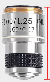
Presume the beam(100mW) has a rotational symmetry intensity then we put it on a planar surface to integrate from r = 0 to r = r0, where r0 is the half-width of the laser beam , and we used an objective with NA = 1.25:
# Constants
c = 3e8 #light speed
Pi = 100e-3 #Input optical power(100mW)
a = mp.mpf("3e-6")  # Radius of particles (3um)
n_p = mp.mpf("1.5")  # Refractive index of particles (glass)
n_m = mp.mpf("1.33")  # Refractive index of medium (water)
n_i = mp.mpf("1.515")  # Refractive index of medium (oil)
NA = mp.mpf("1.25")  # Numerical aperture (objective)
f = mp.mpf("0.3e-3")  # Focal length of objective (WD0.13+Coverslip0.17mm)

# Compute parameters
sin_theta0 = NA / n_i
cos_theta0 = mp.sqrt(1 - sin_theta0**2)
tan_theta0 = sin_theta0 / cos_theta0
r0 = f * tan_theta0  # Maximum radial extent

#Build a 3D model with uneven power based on the above parameters using Ashkin scattering formulas.
#...
The result will be like this:


We can see that the optical wall that is closer to the laser source is actually stronger than the other side. Any wrong entrance made it impossible to form a stable capture, if you turned on the laser while it was located in the z-axis like z < -7.5\ um, this will happen:
But don't worry, this can also be useful to confirm if your stable point is far side or closer side around your image point. After this video, the particle(low density compared to the solution) started to become clearer ad smaller, then we are able to know that this stable point is in the far side. This is a 160mm finite microscope system, so I immediately knew that my laser source had a bigger divergence angle than the 160mm system should be.
2. Comparison between NA and annular parameter
For objectives with different NA and beams with different annular proportion \alpha I find that (assume that all beams have the same power):
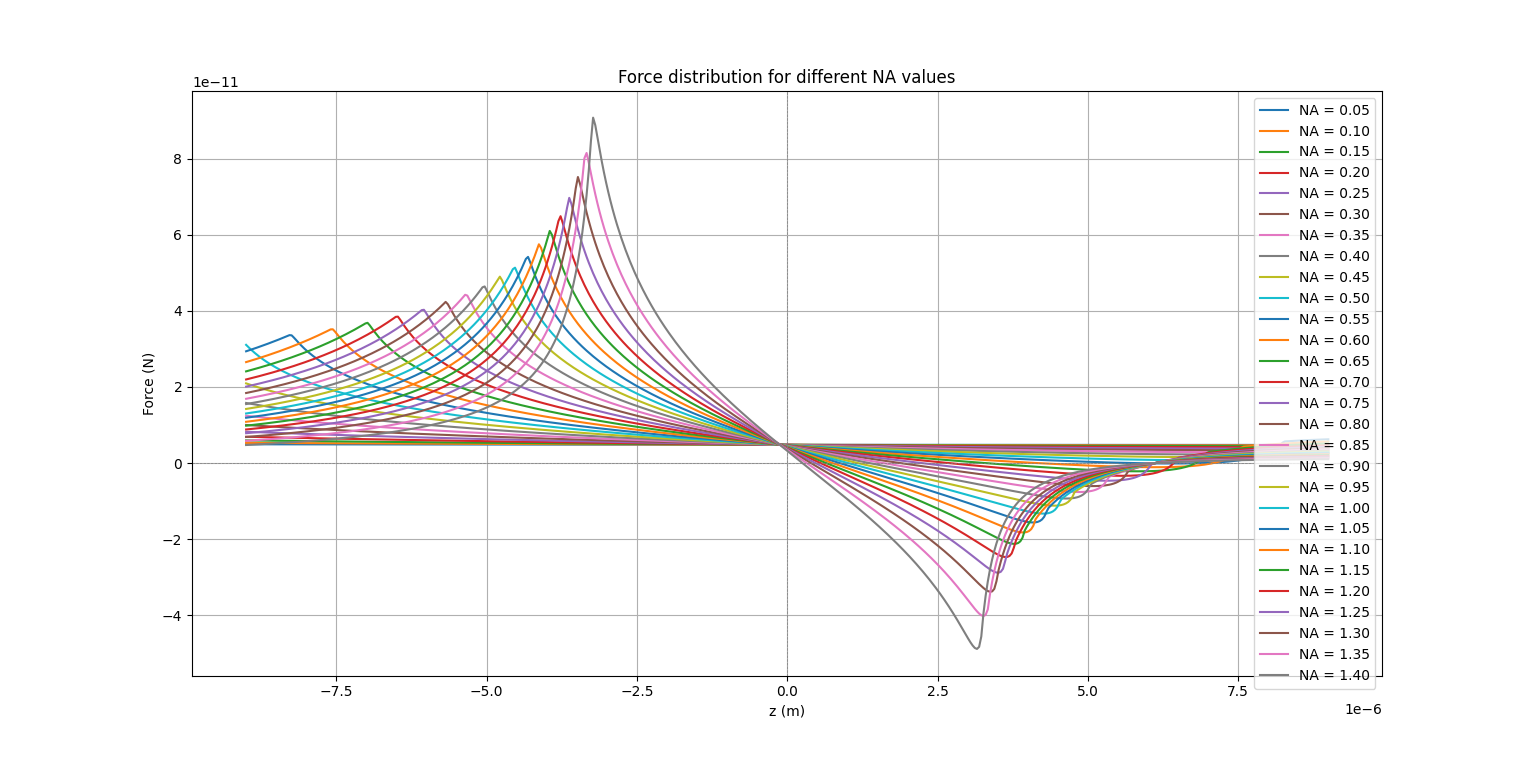
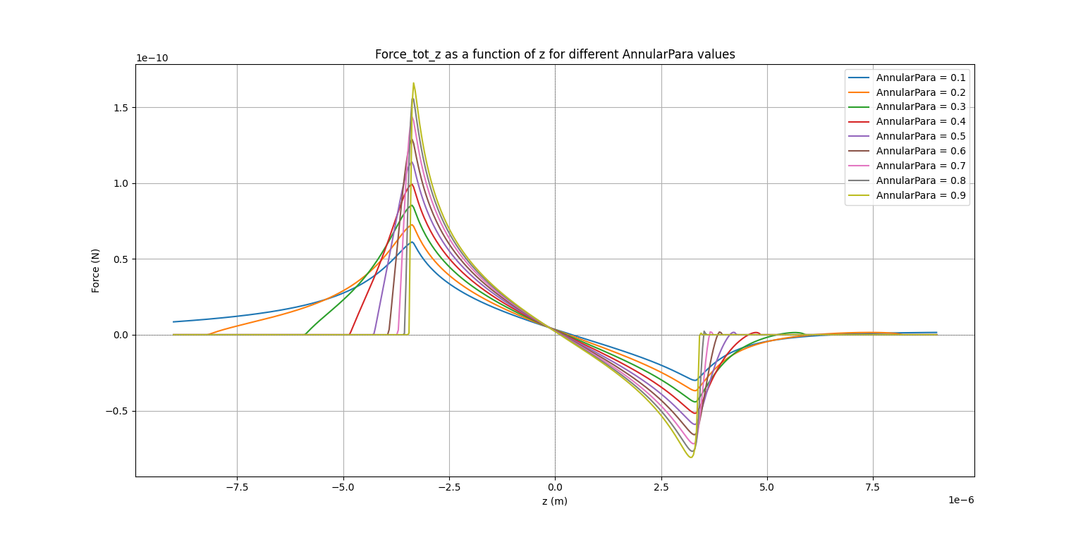
For a higher NA and bigger annular proportion it is easier to trap a particle along the z-axis. But we should note that the optical trap becomes narrower. And it will be very difficult to trap a particle along the z-axis because the length of trap which is just a little bit longer than the diameter of the particle(5um).
For a weak optical trap(Low NA) it looks like this:
3. Problems
To make a homemade optical tweezer, the following problems will appear:
1. The focal plane does not locate at the laser waist.
It is sure that the equilibrium point was a little bit pushed forward because of the strong force along the z-axis. But we can see in the above pictures that it's less than 1um so it can't be the main reason. To be clear, I used a microscope with 160mm tube system, so I made the laser beam had a slight divergence angle to match my objectives. I guess it may be the reason that I just manually adjusted it.
When I can clearly see the particles, it can't be trapped. When it was trapped I can't clearly see the particles.
2. Strong interference fringes:
Without filters and a high pass objective it will be so bright that hurt your eyes and it will be hard to see the other particles which are not trapped. I found a useful tool which can let you to calculate a (xHyL)^m film for a notch filter. It can cut the light within a narrow range of wavelength like 50nm or less.
3. Particles got stuck on the coverslip:
It usually was not caused because of Van De Vaals force, it's because of the electrostatic force. Because the Van De Vaals force is extremely weak compared to electrostatic force and scattering force. If you can't get rid of it from the coverslip by simply adding a strong laser then it should be electrostatic force. You can see this force while moving the sample in the video:
4. Experiment
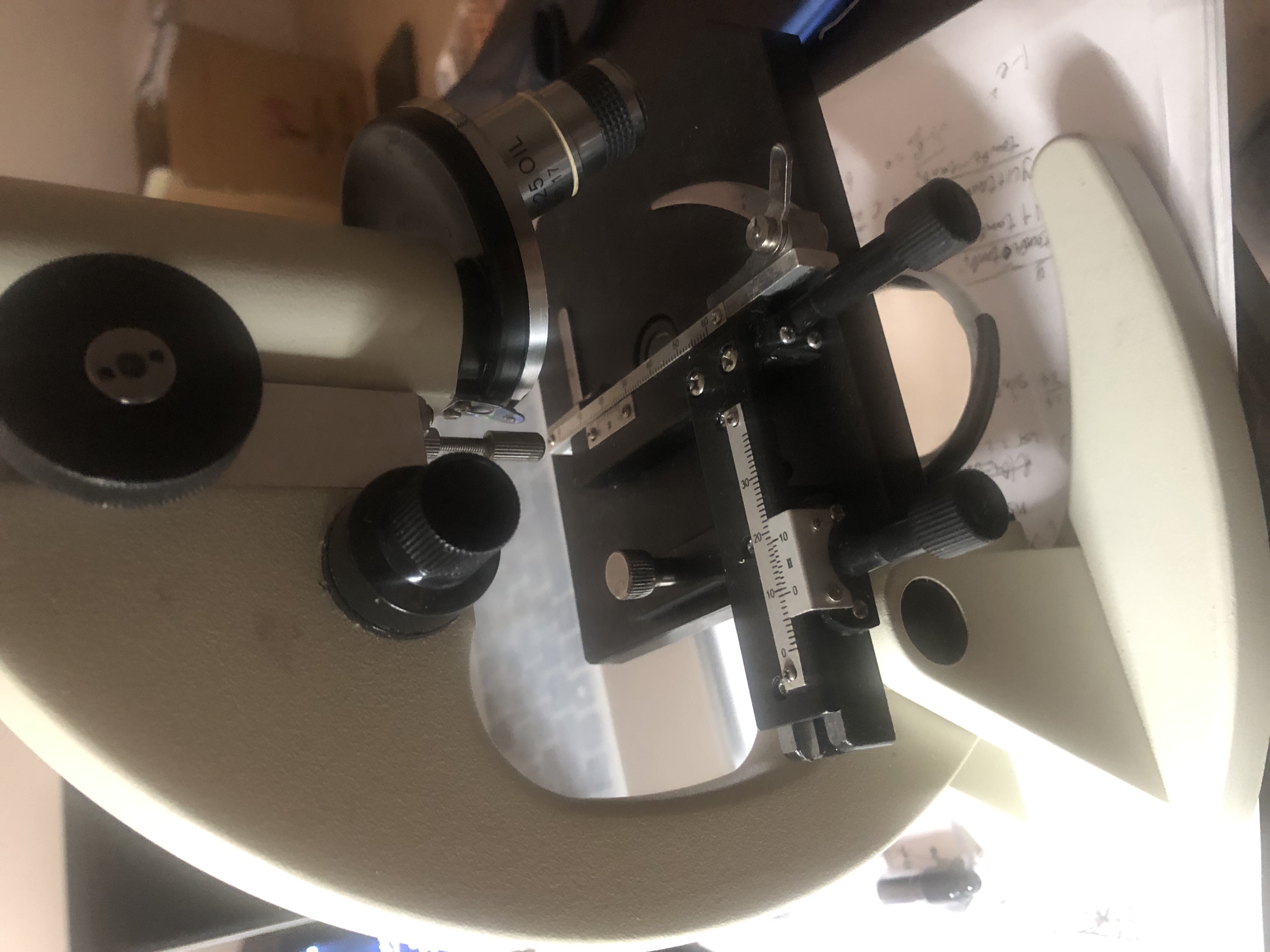
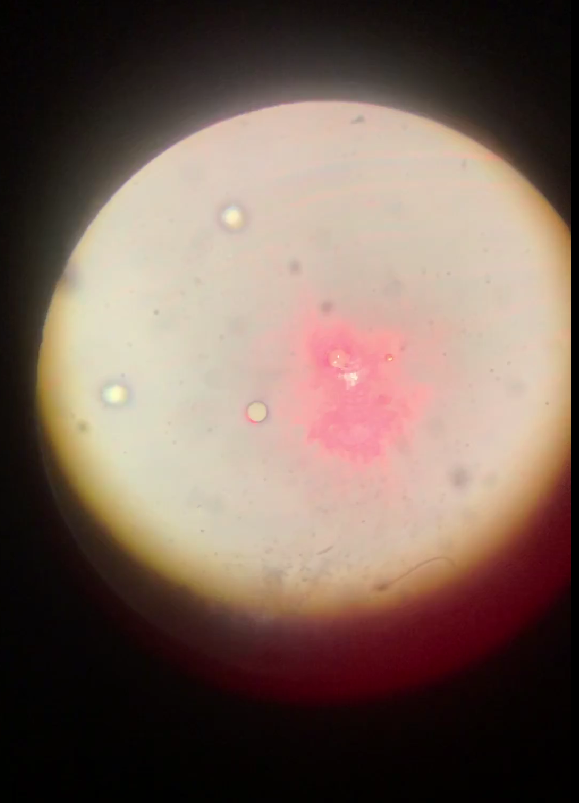
Laser source:
Capturing, releasing and moving manipulation:
To see simulation of Brownian movement, check here: https://youtu.be/SDeDug-orkA

Comment Section